Welcome to Mavo Machine Tool

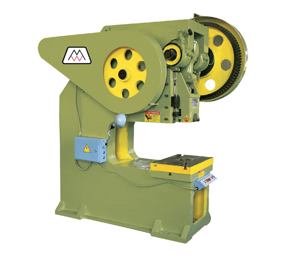
Main technical parameters | |
Nominal force: | 400KN |
Slider stroke: | 100mm |
Slider stroke times: | 50 times / min |
Maximum enclosed height: | 240mm |
Distance adjustment between slide bottom and worktable: | 50mm |
Distance between the center of the slider and the fuselage: | 500mm |
Table size: | Front and rear x left and right=410X650 |
Table hole size: | Diameter 160 |
Dimension of die handle hole on slider: | Diameter x depth=50X70 |
Distance between columns: | 250mm |
Distance between worktable and guide rail: | 290mm |
Thickness of backing plate: | 85mm |
Motor: | 3KW-4 |
Dimensions: | 1600mmX 1000X 2170mm |
Performance characteristics This series of press adopts rigid rotary key clutch, with simple structure, convenient operation and maintenance. It adopts helical gear transmission, stable operation and small impact. The new type J23 open type tilting press changes the sliding bearing (i.e. copper bush) of transmission gear into rolling bearing. After the change, the transmission gear is wear-resistant, avoiding the gear noise caused by the rapid wear of copper bush. | |
Structure and adjustment of main components
The main parts of the press include: 1, body 2, transmission 3, clutch 4, slider 5, brake 6, control
The structure and adjustment of each part are as follows:
1. Fuselage
The machine body is an open double column C-type integral casting part. There is a rectangular blanking hole with a circular shape in the middle on the working table of the machine body to drop the workpiece or waste. The worktable base plate is installed on the worktable of the fuselage, which is fixed on the worktable with bolts, and T-shaped groove is planed on the base plate for installing the die
It's useful. The left and right guide rails are fastened on the fuselage with screws, and the V-shaped groove of the guide rail is used to ensure the accuracy of the vertical movement of the slider, so the slider and the guide rail should maintain a certain gap (0.05-0.09mm), which can be achieved by adjusting the left and right guide rails. When adjusting the clearance, first open the hold down screw, twist the left and right screws, adjust the distance between the left and right guide rails until the clearance between the slider and the guide rail meets the requirements, and then tighten the hold down screw. The crankshaft bearing is a rare earth alloy sleeve, which is mounted on the left and right bearing seats and fixed by fastening bolts. The crankshaft rotates in the rare earth alloy sleeve. There are two ∮ 190 holes in the rear of the fuselage to support the left and right bearing seats with 6216 bearings.
2. Transmission device
The transmission system is powered by a motor mounted on the upper rear of the fuselage. Under the condition of idling, the motor drives the flywheel through the V-belt of the small pulley, rotates through the transmission shaft, drives the big gear through the small gear, rotates the crankshaft through the clutch mechanism of the big gear and the crankshaft, and makes the slider move up and down with the help of the eccentricity of the crankshaft.
3. Clutch
The clutch component is located at the right end of the crankshaft. The rotating key of the clutch is a semicircle key, and the rotating key is normally open through the action of the tension spring. When the head of the control device is against the lever of the clutch, the working key is hidden in the key socket of the clutch, so that the working key is normally closed. The opening and closing of the working key realizes the separation and cooperation of the clutch, so that the work of the slider can be controlled.
4. Slider
The sliding block is located between the guide rails of the fuselage, and the sliding block moves up and down in a straight line in the V-groove of the guide rail through the rotary motion of the crankshaft. The connection between the slider and the crankshaft is that the connecting rod and the connecting rod cap are installed on the shaft through a pair of bearing shells. The connecting rod and the connecting rod screw are connected by saw tooth thread, and the other end of the connecting rod screw is ball head type. A safety block is arranged between the ball bearing pad and the spherical cover plate under the ball bearing pad. When the press is overloaded, the safety block collapses to ensure the safety of the equipment. In order to ensure a certain clearance when the ball head moves, a gasket is placed between the slider and the spherical cover plate, and the clearance required for the ball head rotation is adjusted by increasing or decreasing the thickness. The distance between the bottom surface of the slide block and the plane of the worktable can be adjusted by rotating screws to meet the requirements of die distance. Before adjustment, exit the locking sleeve screw and loosen the fastening sleeve. After adjustment, lock the connecting rod screw with the locking sleeve to prevent the connecting rod screw from turning and loosening. The die holder is used to hold the die holder. A ∮ 60mm die holder hole is made between the die holder and the slider. The die holder is fixed on the slider with stud bolts, and then the die holder is pressed with square head cylindrical screws to prevent the die from turning and moving downward. The slide block is equipped with a return plate. When the slide block moves upward, the return plate touches the return head installed on the machine body, and the stamping products or waste materials fall off from the die.
5. Brake
The brake wheel is round and fixed on the left end of the crankshaft with a key. It is a continuous brake. The brake belt wound on the brake wheel is made of mild steel sheet, and the inner surface is riveted with copper wire asbestos brake belt. One end of the brake band is riveted with a steel plate, which is installed on the machine body with a pin, and the other end is riveted with a pull rod. The screw passes through the spring sleeve and is connected with a nut. The spring is installed on it to adjust the spring tension and generate the required braking torque on the brake, so as to make the sliding block move up and down smoothly. When the braking force works normally, the crankshaft stops at the dead center ± 5 ° due to the inertia moment generated when the clutch disengages the slider and the crankshaft stops.
6. Operating mechanism
This machine tool adopts mechanical control mechanism, and uses foot lever to control the slide block for single stamping. The foot pedal is placed on the inner side of the machine tool, one end is fixed on the right foot with a pin shaft, the middle part of the foot pedal is connected with a small shaft to connect the lower pull rod, the lower pull rod and the middle pull rod are connected with clips, and then the pin is connected with the pull rod, the pull rod and the upper pull rod are connected with adjusting nuts, and one end of the lever head is supported with bolts On the fuselage. When stepping down the foot board, the lever contacts and disengages from the clutch lever, the clutch is engaged, and the sliding block works. Stepping on the pedal can make the slider punch continuously until the punch is finished. Whether the position of the lever head is correct or not can be achieved by adjusting the nut.
Copyright: Nanjing Mavo Machine Tool Manufacturing Co., Ltd
Powered by Jiangsu Huohuo Network Co., Ltd